
These instructions have been written for the benefit of those who have obtained a PC board and components from FAR Circuits for my digital setting circles interface circuit. The remaining parts needed for this kit are inexpensive and are readily available from a variety of sources. If you have any electronic construction experience at all, you should find this interface to be easy to build. If you have questions or problems, please leave a comment below and I’ll help as best as I can.
See my software page for a list of software packages known to work with my interface.
Parts List
All the parts can be obtained from Jameco, but I recommend that you purchase the 4 MHz oscillator from Mouser Electronics instead. I’ve seen two of the oscillators provided by Jameco cause trouble. The oscillators from Mouser seem to work more reliably.
Encoder interface parts list
| Component | Description | Jameco Part No. |
|---|---|---|
| U1 | 7805 voltage regulator | 51262 |
| U2 | Programmed PIC16F84/04P microcontroller chip | 145111 |
| 18-pin socket for U2 | 112231 | |
| U3 | MAX232CPE RS-232 level converter | 24811 |
| 16-pin socket for U3 (optional) | 112222 | |
| C1, C4-C7 | 10uF 35V electrolytic capacitor | 94370 |
| C2, C3 | 0.1uF monolithic capacitor | 25523 |
| R1-R13 | 10K-Ohm 1/4 watt resistor | 29912 |
| D1 | 1N4001 diode | 35975 |
| D2 | LED (any small LED will do) (this and R13 are optional) | 94511 |
| OSC1 | 4 MHz TTL crystal clock oscillator | Mouser Stock Number 815-ACO-4-EK |
| Switch (not shown on schematic) | Normally open momentary SPST pushbutton for a reset switch (optional) | 164486 |
Feel free to substitute your own preferences for the connectors, but I highly recommend that you do not wire the encoder or serial cables directly to the board (they’ll break off easily). Use pins and connectors for a sturdier connection. The right-angle DB9F connector for the serial cable is especially good for ensuring a good connection.
Some recommended connectors for the interface PC board
| Description | Jameco Part No. |
|---|---|
| 0.1″ non-polarized connector housing (5-pin) for connecting to the encoders | 163686 |
| 0.1″ non-polarized connector housing (4-pin) for attaching encoder cables to PC board | 100803 |
| D-Subminiature right-angle PC mount DB9F connector | 104978 |
| Female connector pins for housings | 100766 |
| 0.1″ right-angle headers (male pins board-mounted over which the housings fit) | 103271 |
| Pin crimping tool for crimping the female connector pins | 99443 |
| 4-conductor cable (phone wire) for encoder cables | 103430 |
PC Board Parts and Foil Layout
These diagrams are not drawn to scale. If you want to make your own board, download this file. See the readme.txt file in that file for further information.

PC board parts layout

PC board foil side layout
Programming the PIC16F84 Microcontroller
Note: you can purchase a preprogrammed PIC16F84 microcontroller chip–go here for details. The PIC16F84 microcontroller chip requires a bit more attention than simply buying one and popping it into the circuit. First, it must be programmed. A hardware device called a programmer is required for this task. Luckily, this particular chip can be programmed with very simple-to-build hardware. I’m not going to go into details about programming the chip because there is a ton of information on the web about this topic. I will mention that the Oct 98 issue of QST magazine contained an article titled “Using PIC Microcontrollers in Amateur Radio Projects,” by John Hansen (p. 34)–this was the article that got me started on this project. If you choose to program the chip yourself, the firmware file you need for this project is dsc.hex.
Encoders
My interface is capable of working with encoder setups having up to 65535 tics per revolution of the telescope axis. Frankly, a resolution that high is overkill and runs the risk of dropping counts if the telescope is moved quickly. I usually encourage builders to choose encoders that result in somewhere between 4000 and 10000 encoder tics/rev, factoring in any gearing or pulley systems that are used to connect the encoders to the telescope. My own setup uses about 4500 tics/rev for each axis, and I haven’t been able to make the interface drop a count. The S5S and S6S incremental rotary shaft encoders from U.S. Digital should work well with my interface. You don’t need the index or ball-bearing options. U.S. Digital also sells connectors for these encoders, and it might be wise to purchase those as well.
Connecting encoders to your telescope can be a challenge, depending on the design of your mount. Unfortunately, I can’t offer much in the way of help, since the mounts vary so widely. Regardless of the type of mount, it’s important that your encoders always turn whenever the telescope moves, whether manually or by a drive motor.
Before You Start
Construction of this interface is quite straightforward, but there are a few issues worth considering prior to starting. First, this interface has a number of external connections: the serial cable, the encoder cables, and the power supply. Some thought should be given to exactly how you intend to make these connections so that they are solid and reliable. I’ve designed the PC board so that you can install 0.1″ male headers at the encoder and power connections, and use 0.1″ connector housings with crimp pins on the ends of the cables. This sort of arrangement is much stronger and more reliable than soldering the wires directly to the board.
Similarly, the serial connection is laid out so you can use a straight or right-angle pc-board-mount DB9 connector. Pins 1, 4, and 6 are connected via traces on the circuit board, as are pins 7 and 8, to accommodate software that expects serial handshaking to be implemented. If you only use the connections for pins 2, 3, and 5 on the board, make sure that you connect pins 1, 4, and 6, and pins 7 and 8, at some other point in the cable to achieve the same effect.
It’s very important to make sure that you make the encoder connections correctly. The encoder connections are labeled on the PC board for each of the two encoders. There are typically five pins on an encoder, labeled Ch. B, +5V, Ch. A, N/C, and GND. Sometimes the N/C pin is labeled Index, but my encoder interface circuit does not use the index signal. If your encoders have index pins, leave those pins unconnected.
Similarly, the interface PC board has five holes for connecting each encoder, with the same labels. On the PC board, the N/C hole for each encoder is connected to the GND hole next to it. This allows you to use a four-pin male header and connector housing rather than a five-pin, if you desire (if you use a four-pin connector, mount it in the holes for Ch. B, +5V, Ch. A, and N/C. The N/C hole will serve as your ground and should connect to the GND pin on your encoder).

There is also a place on the PC board for connecting a reset switch. It’s labeled “RESET” and is located between C7 and R11. If you use a reset switch, it should be a normally-open momentary SPST pushbutton switch. Pressing and releasing it restarts the software in the microcontroller. If the interface is not functioning correctly, resetting it will usually fix the problem.
Parts Orientation
Construction of the interface is not difficult. The parts may be placed on the board in nearly any order. Make sure to note the polarity of the diodes, the electrolytic capacitors, the IC’s, the voltage regulator, and the oscillator.
- The diode will have a silver band on one end. Mount the diode on the board so that the silver band on the diode is aligned with the band on the diode legend on the board.
- U1, the voltage regulator, should be mounted so that the metal tab with the hole is on the side away from D1 and toward C1.
- Note the little notches on one end of the legends for U2 and U3. This corresponds to the end of the IC with pin 1. The IC will have a similar notch, or will have a small dot indentation in the corner over pin 1. Make sure that the IC’s are installed with pin 1 where it’s supposed to be.
- The electrolytic capacitors also have a polarization. You’ll notice that one lead is marked with a minus (and is the shorter of the two leads). Similarly, one hole for each electrolytic capacitor is marked with a plus sign on the PC board. Make sure that the positive lead goes in the hole marked with the plus.
- The clock oscillator has tree rounded corners and one that is not. The outline on the PC board is shaped the same. Make sure you insert the oscillator so that its shape matches that on the board.
Construction
Soldering
First things first–good soldering is the key to having this interface work the first time your power it up. About 90% of the problems that builders have in getting their interfaces to work are related to poor soldering. Often the problem is that insufficient heat was used, resulting in solder joints that appear gray and rough instead of shiny and smooth. Other times, too much solder is used, and solder bridges are formed that connect components that shouldn’t be connected. Sometimes, joints are left unsoldered.
In case you aren’t sure you can tell the difference between bad soldering and good soldering, here are examples of each:

Bad solder joints

Better solder joints
Elecraft, a maker of high-quality ham radio kits, has an excellent tech note on its web site regarding soldering technique. You can find the article by accessing their Tech Notes page from their main page and scrolling down the Tech Notes page to find the “soldering tutorial” link.
Parts Installation
The order in which you install the parts isn’t critical. Here’s what I’d recommend:
- First, install the sockets for the IC’s. You don’t have to use a socket for the MAX232 (though I recommend it), but do use a socket for the PIC16F84 so you can remove it and reprogram it at a later time if there is an update to the program or you choose to modify it. Make sure you orient the sockets according to the outlines on the board. Wait until last, though, to install the IC’s in their sockets.
- Next, install the resistors. They should lie flat on the board. Resistors do not have a polarity. Either lead can go in either hole.
- Next, install the 0.1 mF capacitors. They do not have a polarity so either lead can go in either hole.
- Now install the electrolytic capacitors. Carefully observe the polarity as explained previously.
- Install the diodes, the voltage regulator (U1), and the oscillator. Again, make certain you’ve installed them with the proper polarity, as explained previously.
- Now install your choice of connectors for the power, the encoders, and the serial connection.
- Install the reset switch if desired.
- Finally, install the IC’s in their sockets, making certain they are installed in the proper orientation. Make sure you program the PIC16F84 if you haven’t already (and if you didn’t buy it preprogrammed from FAR Circuits).
Check all your solder joints. They should look smooth and shiny. If they don’t, give them a bit of heat with the iron to remelt them. Also, check for solder bridges (solder connecting two points that should not be connected).
Testing
The basic approach to testing the interface is to hook everything up and see if it works. I’ve written a small test program called EkBoxTester that you can download to aid in testing. EkBoxTester requires Microsoft .Net 4.0 to be installed on your computer. EkBoxTester consists of a single executable file (EkBoxTester.exe) that can be run from wherever you want. There is no installer–just download and run it. (The source code for EkBoxTester can be downloaded from here. It was written using Microsoft Visual C# 2010 Express Edition–a free but reasonably complete development environment for writing .Net applications in C#.)
When you launch EkBoxTester, the following window appears:
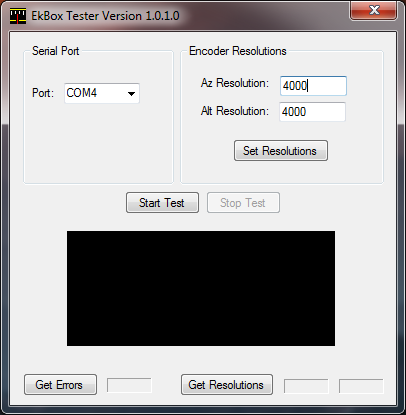
It’s pretty simple to use. Before you do anything else, select the COM port to which your interface is connected. Once you do that, you can do any of the following:
- enter encoder resolutions in the “Az Resolution” and “Alt Resolution” fields and click the “Set Resolutions” button to send those resolutions to the EkBox
- click the “Get Errors” button to read the number of errors in the EkBox (usually zero)
- click the “Get Resolutions” button to read and display the encoder resolutions from the EkBox
- click the “Start Test” button to begin reading and displaying the encoder positions
If you click the “Start Test” button, the EkBox Tester will begin reading and displaying the raw encoder positions coming from the EkBox. The numbers will be displayed in red as you can see below. The numbers will continuously update as you move the encoders until you click the “Stop Test” button. Note that clicking the “Start Test” button doesn’t automatically initialize the encoder resolutions–whatever resolutions are already in the EkBox will be used.
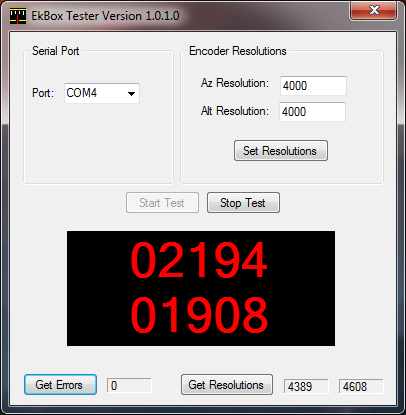
If you don’t have any encoders connected, you’ll still see the red numbers but they will not change (obviously), but this is an indicator that things on the board appear to be working correctly.
Once you’re finished, click the “Stop Test” button, or just exit the program by clicking the red X in the top right corner.
You can also use a communications program such as Hyperterminal on your PC to test the interface. Connect your interface to your PC and configure Hyperterminal to talk to the correct COM port using 9600 baud, 8 bits, 1 stop bit, no parity, and no flow control (handshaking). Then, in Hyperterminal, type the (uppercase) letter Q (note that it won’t appear on your screen unless you turn local echo on, because the interface doesn’t echo the characters sent to it). You should see “+00000 +00000” appear. If so, the communications are working correctly. Next, if you have encoders connected to your interface, turn each encoder a little and type Q again. The numbers that appear on your screen shouldnow be nonzero. If they’re still zero, check your encoder connections.
If the interface doesn’t appear to be working properly, first check all the connectors to make sure that they are properly connected and that they are firmly seated. Next, make sure that you’re supplying the interface with power. A 9V transistor battery is sufficient to power the interface, but it must be a fresh battery. You can also use other voltage sources, but make sure that the voltage is at least 9V (but preferably no more than about 15V) and capable of supplying 50 mA of current on a continuous basis. Nearly all battery configurations that result in 9V or more can supply this moderate amount of current. If possible, measure the output of U1, the voltage regulator, to verify that it’s supplying 5V to the rest of the circuit (you can measure this at pin 14 of U2).
If you’re still having trouble, verify that all the parts have been installed with the proper polarity. Pay special attention to the orientation of U2 and U3. The circuit will not work if either of these is installed backwards. Also, if you have an oscilloscope or frequency counter, see if you can detect the 4 MHz clock signal coming from OSC1 (check at pin 16 of U2).
If everything’s installed correctly, flip the board over and double-check all your soldering. Bad or missing solder joints are the number one cause of problems in this project. Also check for solder bridges that connect things that shouldn’t be connected. Your solder joints should appear shiny and smooth and should completely cover the hole and surround the part leads. Use just enough solder to make the joint, but no more. If you don’t see any obvious solder problems, heat up your iron and reheat each solder joint, and try again.
Configuring Your Software
My software page describes how to use my interface with the software packages that support it.
Getting Help
Leave a comment below if you need assistance or have questions. I’ll do my best to help.
If you wish to modify the circuit or the embedded software, I can provide you with the source files you might need. The circuit diagram and PC board layout were done with a freeware package called Eagle Layout Editor (the lite version) from CadSoft USA. The embedded software was written using Microchip’s MPLAB software (another freeware package). Contact me for details.
Good afternoon,
I build two 3D printers and used my backup Arduino kit for my telescope. Ramps board, drivers, encoders, steppers motors and DS1302 clock included.
I created an App for my Smart phone using MIT APP inventor. All the controlling commands are transmitted via WIFi to an ESP32 Dev Kit. The I2P is connected to interrupt pins 21 and 21 on the Arduino.
Star database is stored on the ESP32 and a star can be selected with the phone.
Time, date and location are set by the phone.
Slew is done by the phone.
Sync and selecting objects can be reading from Stellarium.
When I point my telescope to 0 deg south the code that (I found on the internet) is reading 82 deg. The counters are working 100% on any movement.
In my attempt to read more, I found your page by accident. I am going to play with your idea. I have tried it But the alignment to two stars is missing.
OK, All I want to say is thanks for this information.
Regards
Ockert
Ockert, thank you for your comment. Hope you find my information helpful.