
This variation on my Digital Setting Circles project was created by Craig Combes. He provided the following content so others could recreate his version. Thanks, Craig!
NEWS! FAR Circuits now offers assembled and tested boards that include the programmed PIC16F628A chip as well as the RN-42 bluetooth module. All you should need to do is connect power to the board (which requires a little bit of soldering) and wire the encoders (the board includes an RJ-45 plug that accepts an 8-pin Ethernet connector, so you might need to obtain a crimping tool in order to set up the proper connection). I’ve created a short guide that includes information about how to connect to the board via Bluetooth with your Windows PC. It also includes basic checkout and troubleshooting instructions, in case you need them. You can download the guide here.
For ordering information, go here.
Many people use Dave’s serial DSC board with a serial to Bluetooth adapter and that can get quite pricey, large and power hungry. So I adapted Dave’s design to skip the RS232 circuit and go straight to Bluetooth. In the process, I decided to change the PIC to a less expensive, and more recent chip: the 16F628A, which Dave had code for already. I made some minor tweaks to the code to eliminate some pull up resistors.
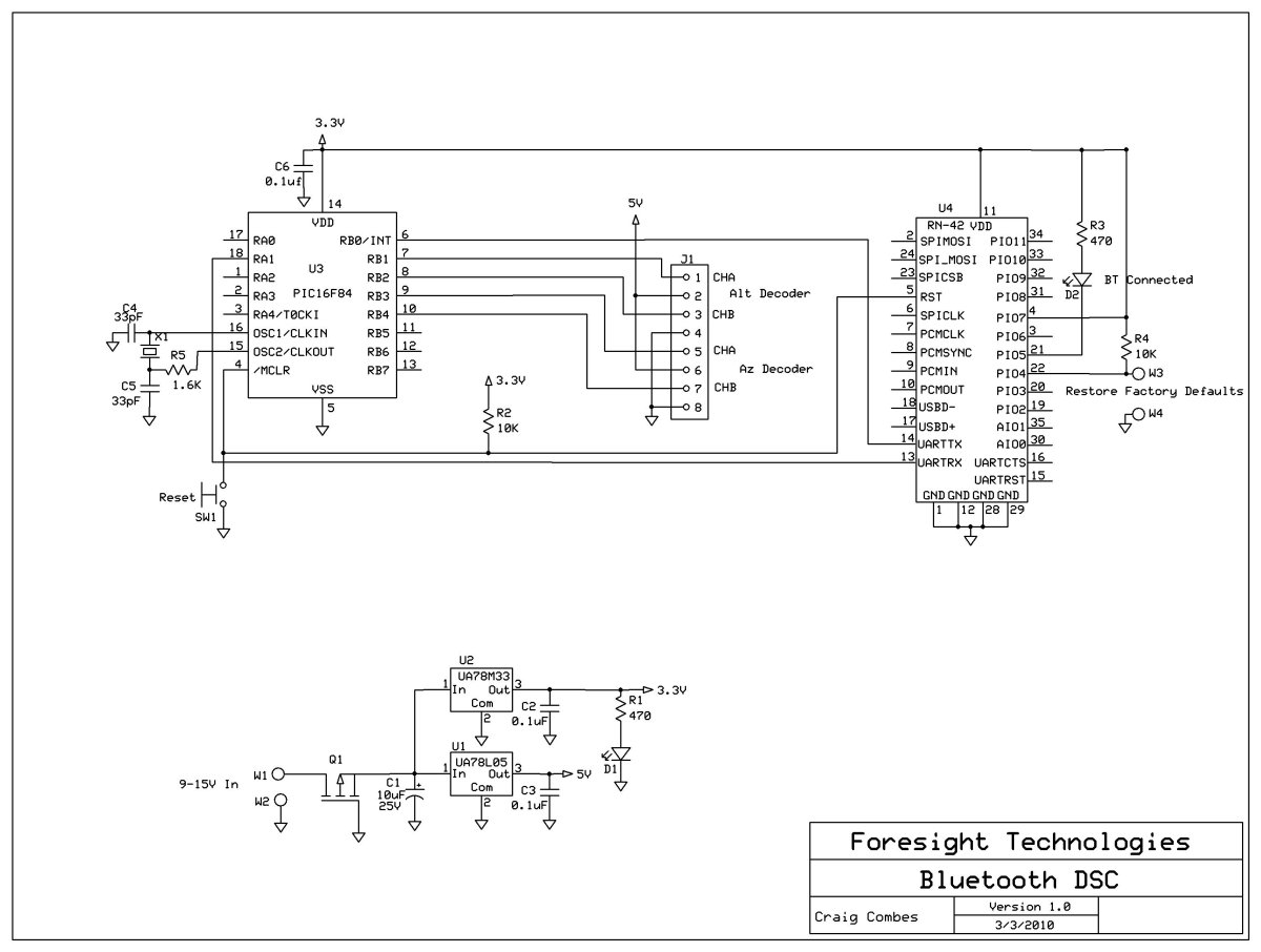
The new design uses a 5 volt regulator (to make sure the encoders are happy) and a 3.3 volt regulator to supply everything else (the Bluetooth module needs 3.3v). I used a MOSFET for polarity protection to reduce the input voltage requirement. I also replaced the oscillator module with a crystal to reduce cost and power consumption. The Bluetooth module is a surface mount device and the boards I created have 11 pads to solder for this device. Most of the other components (not the PIC) are surface mount also, but there aren’t many of them and their are only a few pins maximum per component to solder, so it’s not difficult.
(Dave’s comment: it’s important to use the 16F628A PIC chip, which can operate at 3.3V, and not the 16F628 PIC chip which cannot.)
The Bluetooth module is the RN-42 from Roving Networks, which only uses 30ma when transmitting, 3ma when “sniffing” and 26ua when sleeping. I have it configured to communicate at 9600 baud. For more info on the RN-42, you can go here:
D1 is the power on indicator LED. SW1 is the reset button for the RN-42 and the PIC. D2 is the status indicator light for the RN-42. D2 blinks until connected, then it stays on.
Here is the schematic diagram (click to enlarge):
The parts list:
| Part | Description | Mouser Part No. | Price |
|---|---|---|---|
| R1 & R3 | 470 ohm resistor | ||
| R2 & R4 | 10k ohm resistor | ||
| R5 | 1.6k ohm resistor | ||
| C1 | 10uF 15V aluminum electrolytic capacitor | ||
| C2, C3, C6 | 0.1uF 10V (or greater) capacitor | ||
| C4, C5 | 33pF 10V (or greater) capacitor | ||
| D1, D2 | LED | ||
| Q1 | P-Channel MOSFET | 863-NTR1P02T1G | $0.36 |
| U1 | UA78L05 5v Voltage Regulator | 595-UA78L05ACPK | $0.48 |
| U2 | UA78M33 3.3v Voltage Regulator | 595-UA78M33CDCYR | $0.60 |
| U3 | Microchip PIC16F628A Microcontroller | 579-PIC16F628A-I/P | $2.07 |
| U4 | Roving Networks RN-42 Bluetooth Module | 765-RN-42 | $19.95 |
| SW1 | Normally Open Pushbutton switch | ||
| J1 | Dual RJ-11 jack | ||
| X1 | Crystal ±20ppm 4MHZ Fundamental | 815-ABL-4-B2 | $0.39 |
Right-click here to download the .hex file for the PIC.
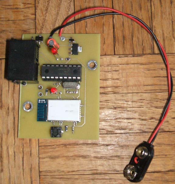
Here’s a picture of the completed board (click to enlarge):
Hello!
Many thanks for this beautifull project description. Verry interesting!
I would like to create a push system for my Dobson using a ESP32 and 2 stepper encoder.
My hardware is OK but I have a problem for the communication with Stellarium or Skycharts.
I would like to be able to understand and adapt your Microchip software in order to use it with ESP32 (ESP32 has Bluetooth and Wifi included).
Is it possible to receive your software not compiled ? (I mean the human readable .c version instead of .hex)
Thank you verry much in advance!
Kigege.
Gerald,
I generally don’t release my source code. In your case, my source code would not be a good choice for a starting point for your project. It is written in assembly language, not c, and is very tailored to the PIC chip it was written for. Trying to port that code to another platform would be harder than starting from scratch.
Good luck –
Dave
I bought the Bluetooth board and it works great.
I used us digital s1 1000 (4000) and skysafari works flawless together. On a other scope the encoders are s1 2048 (8192) it seems to work fine but only half the sky after alignment.
And it jumps to the opposite side of the sky when you move the scope pass a certain of the sky move it back and jumps back and everything is fine.
So the question is how do you change the encoder resolution on the Bluetooth board I believe that is the problem as the default is 4000 tick eencoders
Don, it sounds like SkySafari isn’t setting the encoder counts, so you’ll have to do it manually. One way would be to connect the board to your PC and run the EkBox Tester program that you can download from my “Building the Circuit” page: https://eksfiles.net/digital-setting-circles/building-the-circuit/. That test program allows you to specify the encoder resolutions, and they’ll be stored in the chip until you change them.
Dave
Thanks for speedy reply so connect using the Bluetooth and run e box tester on PC and change encoders resolution
Thank you
Don